Serial Output
The SMART System can output system status information and pass-level measurements of bat call parameters via its two serial ports.
Serial Port Specifications
The SMART Controller has two male, DB-9 serial ports that support RS-232, RS-422, or RS-485 protocols. By default, both ports are configured for RS-232.
Both ports are DTE ports. To connect one of the SMART Controller's serial ports to another device with a DTE serial port, such as another computer, you should use a null modem female-to-female cross-over cable or adapter.
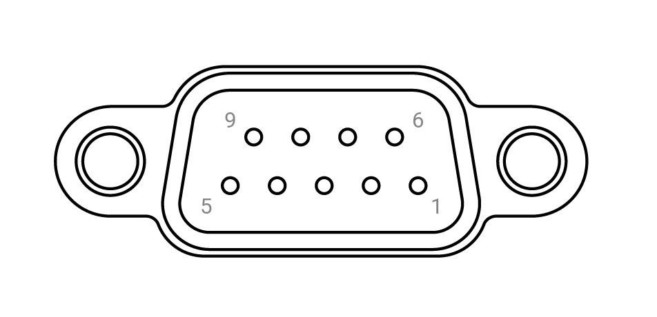
| Pin | RS-232 | RS-422 | RS-485 |
|---|---|---|---|
| 1 | DCD | TX- | TX-/RX- |
| 2 | RX | TX+ | TX+/RX+ |
| 3 | TX | RX+ | NC |
| 4 | DTR | RX- | NC |
| 5 | GND | GND | GND |
| 6 | DSR | NC | NC |
| 7 | RTS | NC | NC |
| 8 | CTS | NC | NC |
| 9 | RI | NC | NC |
NC = Not Connected
Serial Messages
Two types of serial messages can be generated:
- Event Messages
- Event messages are output each time a triggered recording is completed and the results.csv file is updated. These messages can contain an optional text string and any selected fields from the results.csv file, with the exception of the species ID field.
- Poll Messages
- Poll messages are output at regular intervals. These contain an optional text string and status information about the SMART System.